|
Blender Materials: Light Emission |
|
Introduction
An animated scene uses light to influence how the objects are viewed and how visible they are. Blender provides various options for lights. To start, when you start a project, Blender adds a default light. You can keep it, change it, delete it, or replace it.
 Practical Learning: Introducing the Project
- Start Blender
- In the Properties window, click the Object button

Practical Learning: Modeling a Room
- In the Tools window, click the Create tab
- In the Create tab of the Tools window, click Plane
- To change the name of the shape, in the Properties window, click Plane to select the name
- Type Back Wall and press Enter
- In the Transform section, change the following values:
Location - Y:  8
           Z:  5
Rotation - X: 90
Scale    - X: 8
           Y: 5
- To add a new plane, in the Create tab of the Tools window, click Plane
- While the plane is still selected, in the Properties window, change the following values:
Name       Left Wall
Location - X: -8
           Z:  5
Rotation - Y: 90
Scale    - X: 5
           Y: 8
- To add a new plane, on the menu below the work area, click Add -> Mesh -> Plane
- While the plane is still selected, in the Properties window, change the following values
Name:      Floor
Location - Z: .01
Scale    - X: 11
           Y: 11
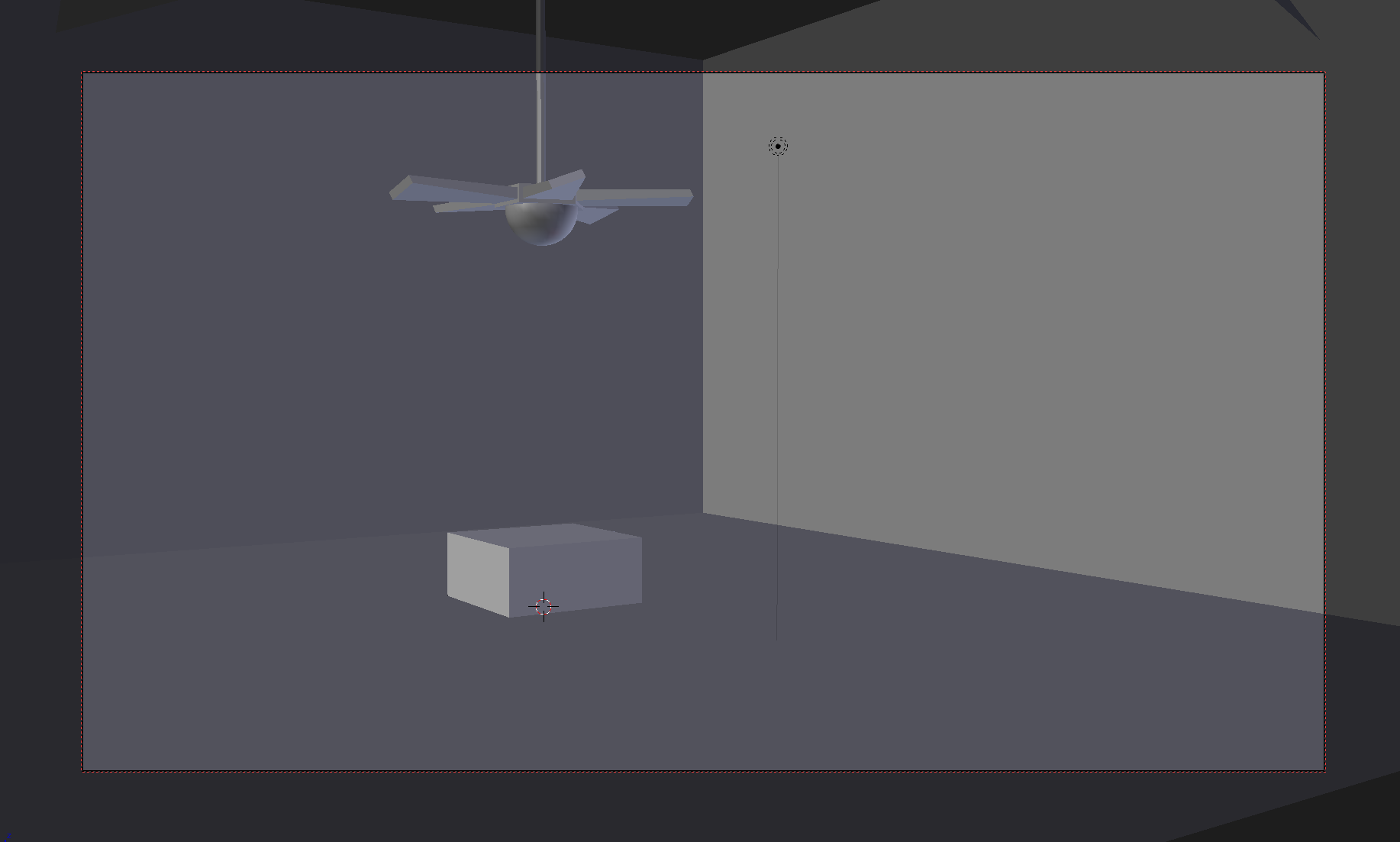
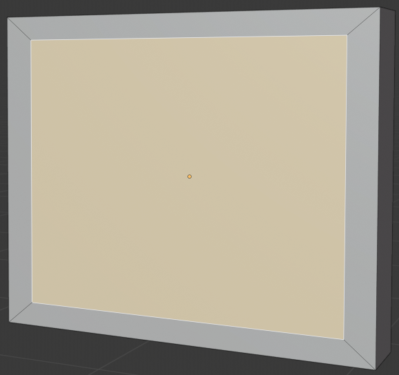
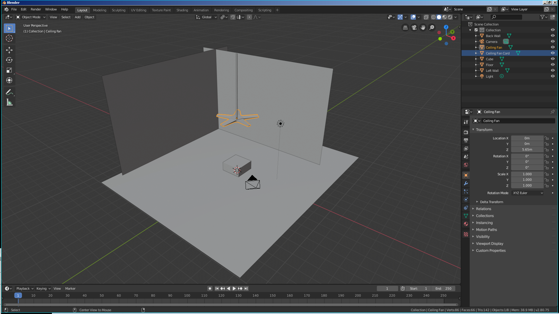
- Zoom in to get a better view of the scene. Here is an example:
Practical Learning: Modeling a Ceiling Fan
- Position the mouse in the work area and press Shift + A -> Mesh -> Cylinder
- In the Add Cylinder section below the Tools window, change the following values
Vertices:  8
Radius:   .065
Depth:     6
Location - Z: 8.5
- On the menu bar of the 3D View, click Add -> Mesh -> UV Sphere
- In the Add UV Sphere section below the Tools window, change the following values:
Size:     .5
Location - Z: 5.5
- While the sphere is selected, position the mouse in the work area, press M and, in the Layers window, click the second box
- On the menu bar of the 3D View, in the Visible Layers section, click the second button
- Zoom in to see as much as possible of the sphere
- In the Numeric Pad of the keyboard, press 1 to access the front view
- Press 5 to display the sphere in orthographic view
- Press Tab to display in Edit Mode
- Press Z to display in Wireframe mode
- Press A to deselect everything
- Press B to prepare to box-select
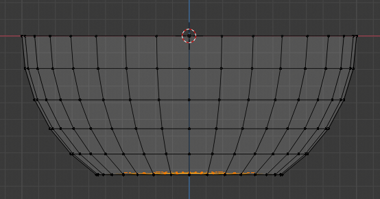
- Draw a rectangle that selects the top lines excluding the middle line and the line just above it:
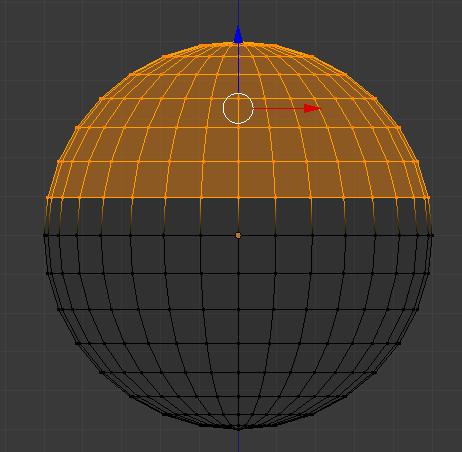
- Press X
- In the menu that appears, click Faces:
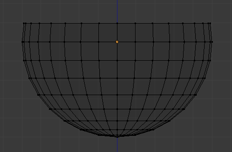
- Zoom out to see less of the sphere
- Press Tab to display the Object Mode
- In the Numeric Pad, press 5 to return to the perspective view
- Press Z to return to the Solid view
- In the Properties window, change the name to Ceiling Light and press Enter
- In the Tools window, click the Tools tab and click Smooth
- While the object is selected, position the mouse in the work area, press M and, in the Layers window, click the first box
- In the Tools window, click the Create tab
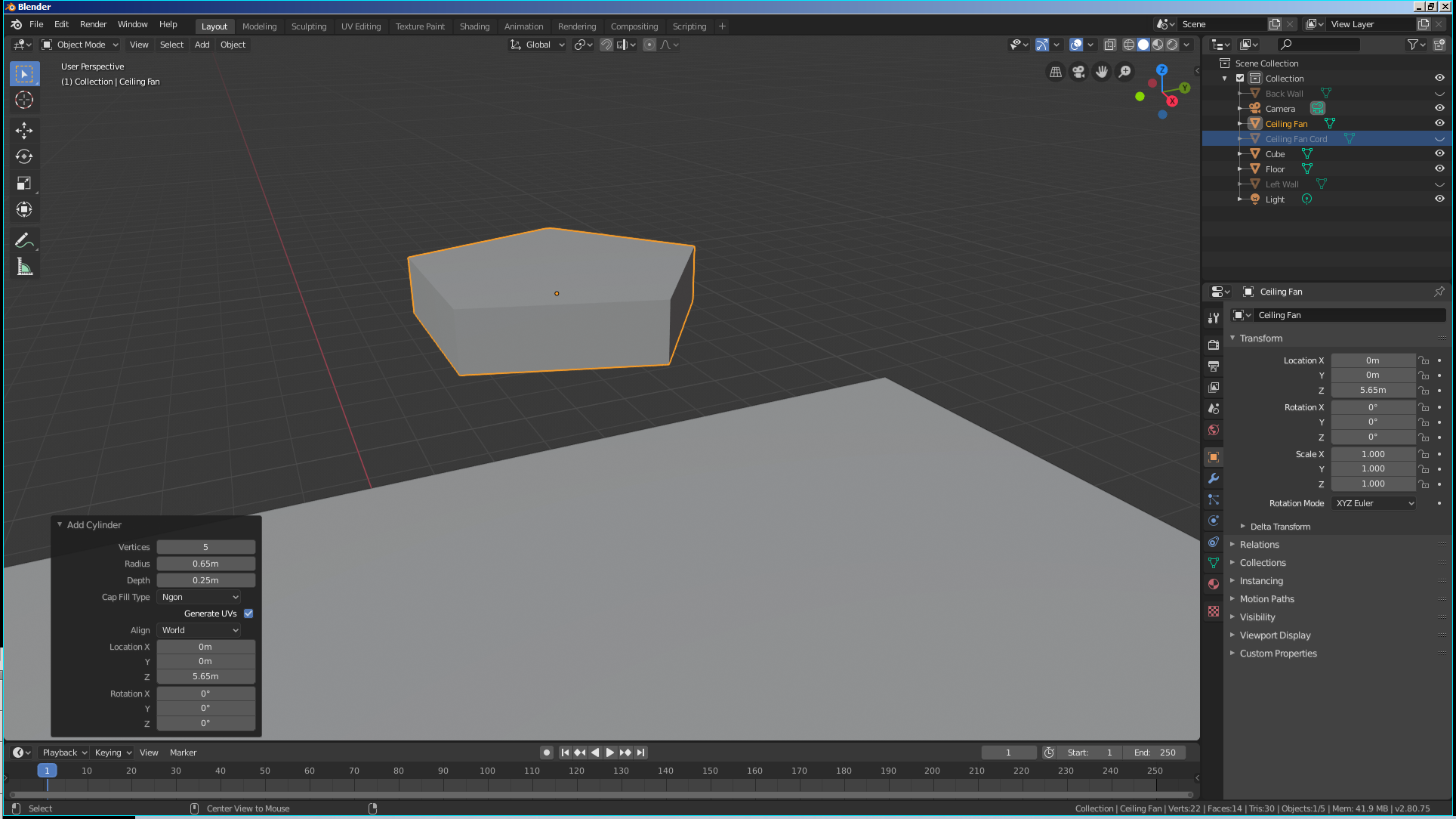
- In the Tools window, click Cylinder
- In the Add Cylinder section below the Tools window, change the following values
Vertices:   5
Radius:    .65
Depth:     .25
Location - Z: 5.65
- In the Object section of the Properties window, change the name to Ceiling Fan and press Enter
- Zoom in to see as much as possible of the hexagon:
- Press Tab to display in Edit Mode
- On the menu bar of the 3D-View, click the Face Select button

- Right-click one of the vertical faces to select it
- Press I to create an inset on the selected face
- Type .05 and press Enter:
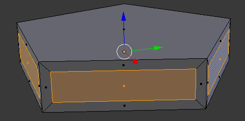
- Using the same technique, create an inset on each vertical face:
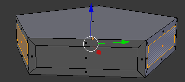
- By pressing and holding Shift while right-clicking, select each of the inside faces you had created to select all of them:
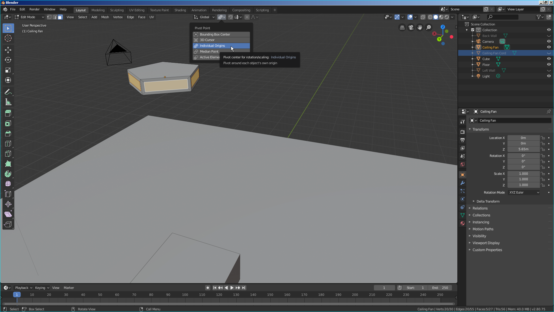
- On the menu bar of the 3D View, click the Pivot button and select Individual Origins:
- Zoom out to display the hexagon far from you
- Press E to extrude
- Type 1.5
- Press Enter
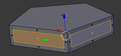
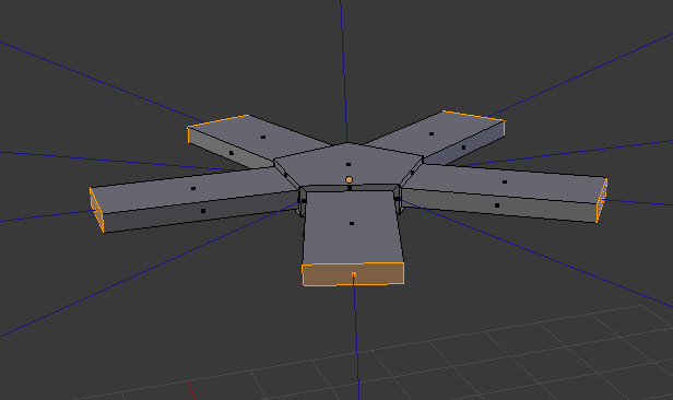
- While the faces are still selected, press S to change their sizes
- Type .75 and press Enter:
- Press R to rotate
- Type -30 and press Enter:
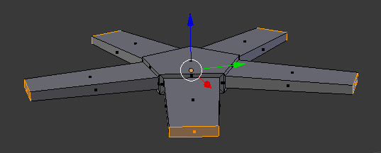
- On the menu bar of the 3D View, click the Pivot button and select Median Point
- Press Tab to return to the Object Mode
- Zoom out to see less of the ceiling fan
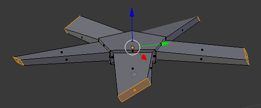
- Press M and, in the Layers window, click the first button
- On the menu bar of the 3D View, in the Visible Layers section, click the first button:
Practical Learning: Creating the Lights
- In the Tools window, click the Create tab and click Plane
- In the Properties window, change the following values
Name:      Local Light
Location - X: -4
           Y: -4
           Z:  10
Rotation - X: 30
           Y: -35
Scale    - X: 2
           Y: 1.5
- In the Tools window, click the Create tab if necessary and click Plane
- In the Properties window, change the following values
Name:      Projected Light
Location - X:   6
           Y:   4
           Z:   10
Rotation - X: -20
           Y:  45
Scale    - X:   2.5
           Y:   3.5
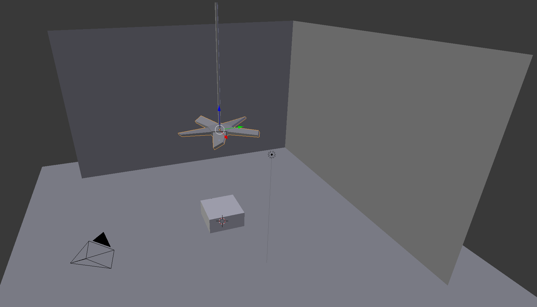
- Position the mouse in the work area and, to display the camera view, in the Numeric Pad, press 0
- Press N to display the Properties Region
- In the Properties Region, click the Lock Camera to View check box
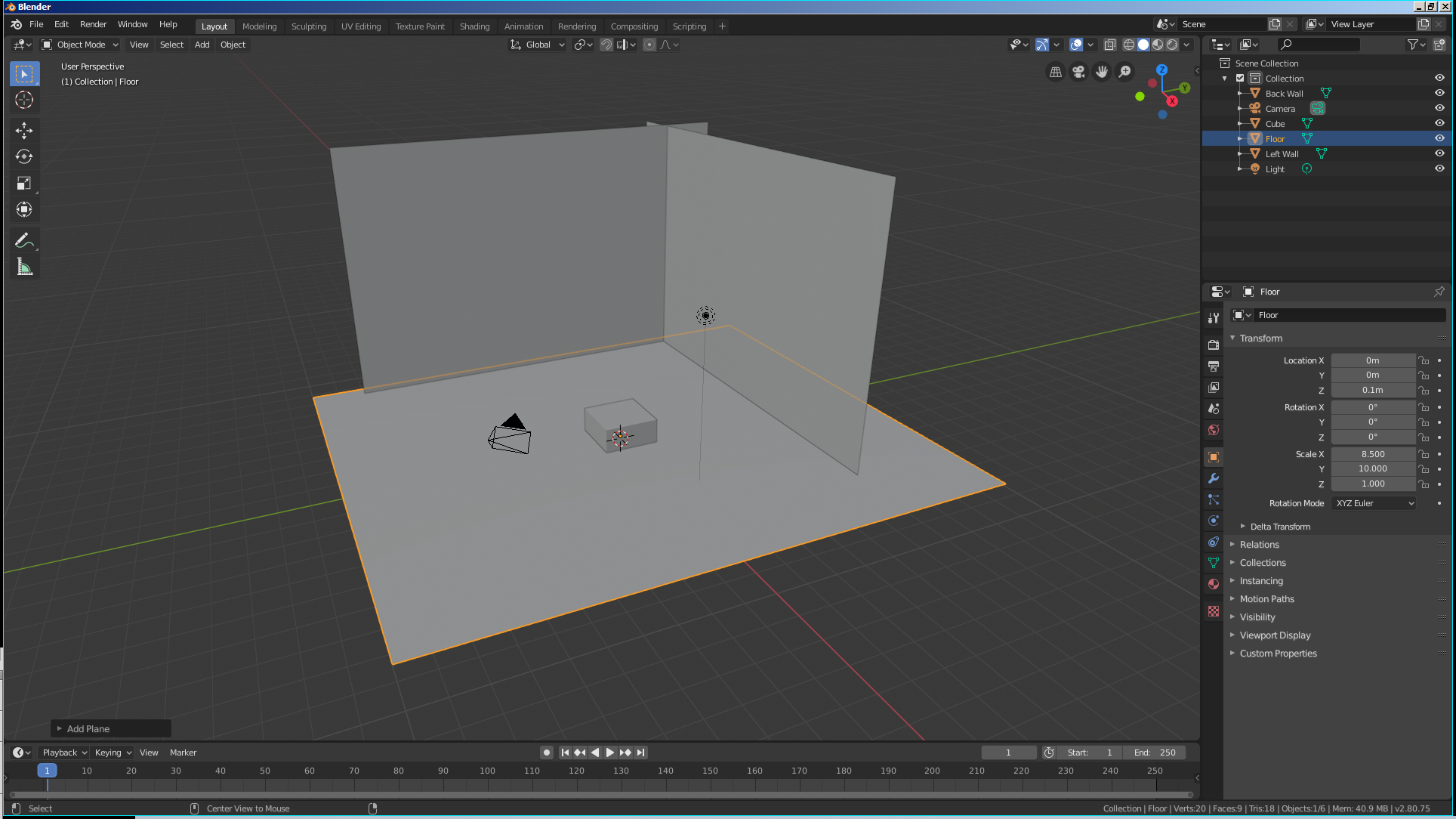
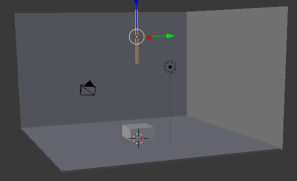
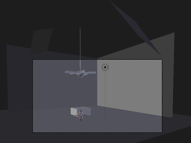
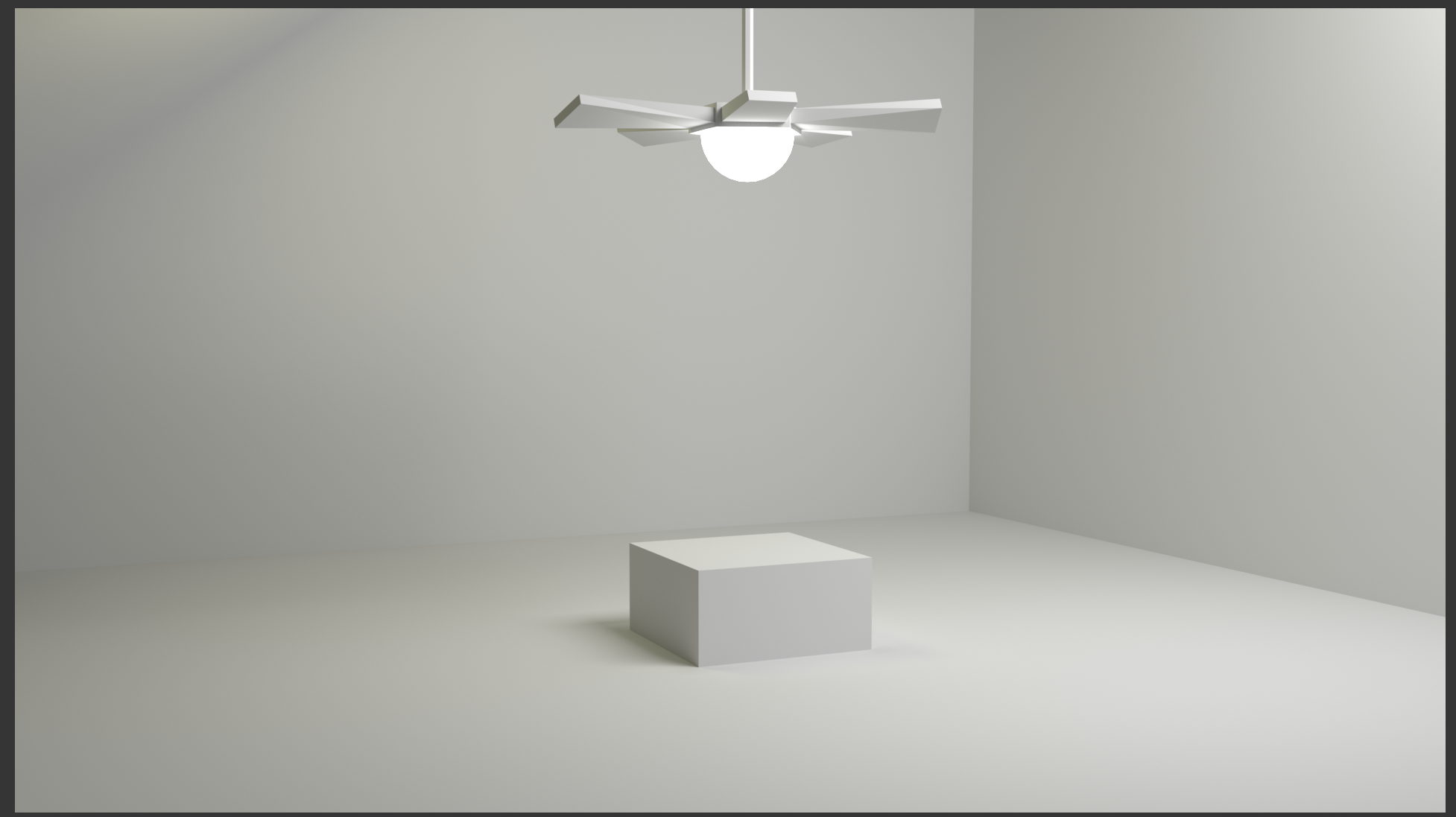
- Use the mouse and the keyboard to position the view so you can see the whole area. Here is an example:
- In the Properties Region, click Lock Camera to View to uncheck it
- Press N to close the Properties Region
- To preview the result, on the top menu, click Render -> Render Image
- After viewing the result, press Esc to return to the 3D View
Creating a Custom Light
To get a custom light, create a shape such as a plane or else. Then apply a shader named Emission to it.
In this exercise, we will ignore or remove the existing lamp (we could have kept it) and use only custom lights to the scene.
Practical Learning: Creating Some Lights
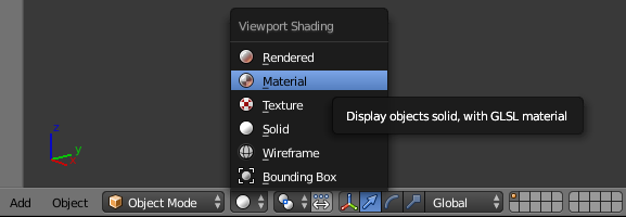
- In the top menu bar, click Blender Render and select Cycles Render
- On the menu bar of the 3D View, click the Viewport Shading button and select Material:
- In the Properties window, click the Render button

- In the Properties window, in the Resolution section, click 50%, type 100 and press Enter
- Click Sampling to expand it
- In the Samples section, set the Render value to 500
- On the scene, right-click the existing light to select it
- Press X to delete
- In the menu that appears, click Delete
- In the Outliner, click Local Light to select it
- In the Properties window, click the Material button

- In the Material section of the Properties window, click New
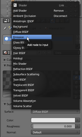
- In the Surface text box, click Diffuse BSDF and, in the menu that appears, click Emission:
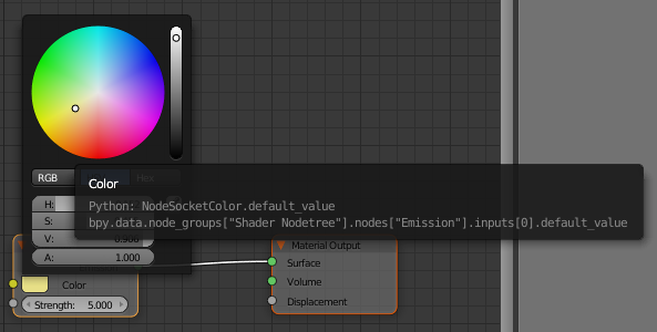
- Change the Strength value to 5 and press Enter
- Click the Color button and select a light-yellow color (I am using R = 0.800, G = 0.800, and B = 0.45):
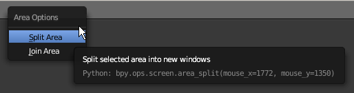
- Right-click the bottom border of the top menu bar and click Split Area:
- Position the mouse somewhere between the middle of the work area and the right border
- Click to confirm. If necessary, resize the windows
- In the bottom-left side of the new window, click the 3D Viewport button and select Node Editor
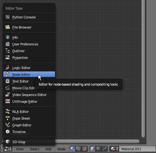 n
n
- Position the mouse inside the new window and press N to close its Properties Region
- Zoom in the Node Editor to get a larger view of its content
- In the Outliner, click Ceiling Light
- On the menu bar of the Node Editor, click New
- In the Properties window, click Diffuse BSDF and, in the menu that appears, click Emission
- In the Node Editor, in the Emission box, change the Strength to 8 and press Enter
- In the Outliner, click Projected Light
- In the Properties window, click the New Button
- In the Node Editor, click the body of Diffuse to select it:
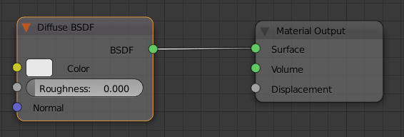
- Press Delete
- On the menu bar of the Node Editor, click Add, position the mouse on Shader, and click Emission:
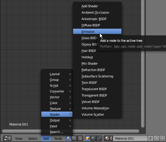
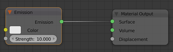
- Position the Emission window to the left of the Output window
- Drag the green button from the Emission window and drop it the green button of Surface in the Material Output window
- In the Emission window, change the Strength to 10
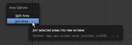
- Right-click the line between the 3D Viewport and the Node Editor
- In the menu that appears, click Join Area:
- Position the mouse in the Node Editor and click (or click the right-pointing arrow)
- In the Properties window, click the Render button
- To preview the result, in the Render section, click the Render button
- After viewing the result, press Esc to close the render view
- In the Outliner, click Floor
- In the Properties window, click the Material button if necessary
In the Material section of the Properties window, click the New button
- Click the Preview button to expand it
- Click the Color button
- Set the RGB color as:
R: .515
G: .515
B: .515
- In the Outliner, click Ceiling Fan
- In the Material section of the Properties window, click the New Button
- In the Properties window, click the Color button
- Click its Hex button and set the color as 3D0C02
- In the work area, right-click the tiny long cylinder above the ceiling fan
- In the Material section of the Properties window, click the New button
- Click the Color button and click RGB
- Set the color value as follows:
R: .025
G: .005
B: .005
- In the work area, right-click the wall on the left side (alternatively, in the Outliner, click Left Wall) to select it
- In the Material section of the Properties window, click the New button
- Click the Color button and set the Hex value to 3366CC
- In the work area, click the right wall (alternatively, in the Outliner, click Back Wall)
- In the Material section of the Properties window, click the New button
- Click Color and set the Hex value to 3399FF and press Enter
- In the work area, right-click the tiny cylinder above the lamp to select it
- In the Properties window, click New and click Color
- Set the Hex value as 3D0C02 and press Enter
- In the Properties window, click the Render button
- To preview the result, in the Render section, click the Render button
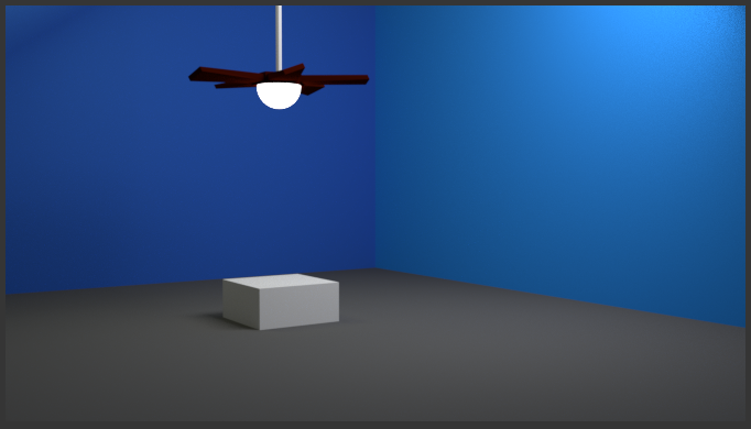
- After viewing the result, press Esc to close the render vieW