 |
Blender Materials: the World |
|
Introduction
In Blender, the world is the environment in which everything exists. In the real world, it primarily consists of the sky whole primary color is blue but can be any other color.
 Practical Learning: Introducing the Project
- Start Blender
- In the Properties window, click the Object button

- In the Outliner, click the Restrict Viewport Visibility butt (the eye) of Lamp to hide it
- In the Outliner, click the Restrict Viewport Visibility butt (the eye) of Camera to hide it
Practical Learning: Starting a Window
- The default cube shoold be selected (if you have doubts, right-click it to select it).
In the Object tab of the Properties window, click Cube to select the name
- Type Sample Window and press Enter
- In the Transform section, change the following values:
Location - X: -4.85
           Y: -.45
           Z: 1.15
Scale    - X: .3
           Y: .05
           Z: .25
- While the cube is selected, position the mouse in the work area, press M and, in the Layers window, click the second box
Practical Learning: Starting the Foundation of a Townhouse
- In the Tools window, click the Create tab
- In the Create tab of the Tools window, click Cube
- In the Transform section of the Properties window, change the following values:
Name:      Foundation
Location - X: -4
           Y:  1
           Z:  .2
Scale    - X: 1.5
		     Y: 1.5
		     Z: .2
Practical Learning: Starting a Townhouse
- In the Tools window, click Create
- In the Create tab of the Tools window, click Cube
- In the Transform section of the Properties window, change the following values:
Location - X: -4
           Y:  1
           Z:  1.65
Scale    - X: 1.5
		     Y: 1.5
           Z: 1.25
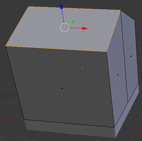
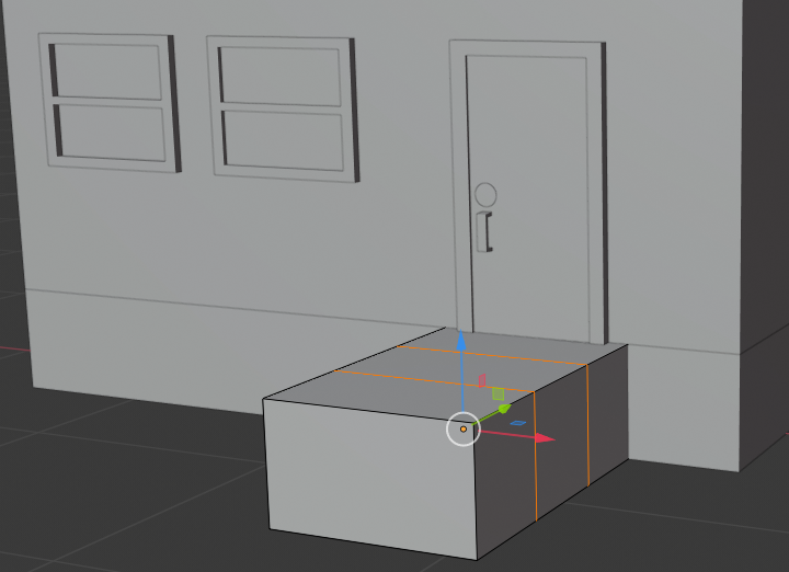
- Position the mouse on the cube and press Tab to switch to Edit Mode
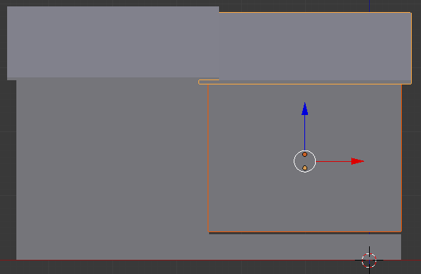
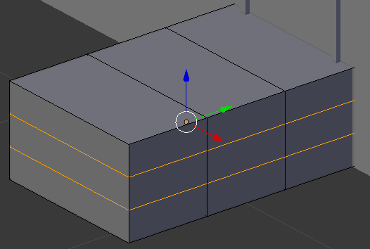
- Position the mouse on the top face, press Ctrl + R and move the mouse to get a line parallel to the red arrow (the X axis)
- Click twice to confirm the cut:

- On the menu bar of the 3D-View, click the Edge Select button

- Right-click the top edge to select it
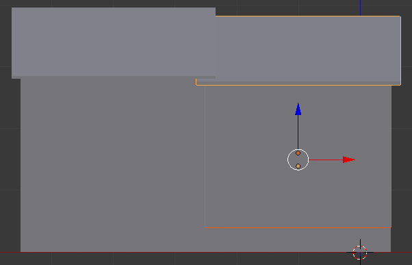
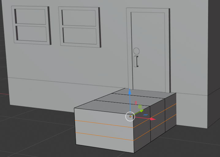
- Press G to move the line
- Press Z to move up
- Type 1 and press Enter:

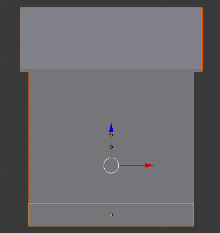
- On the menu bar of the 3D-View, click the Face Select button

- Right-click one of the top two faces:
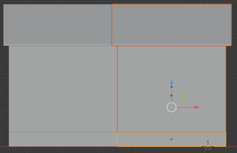
- If necessary, move the view so you can see the other top face.
Press and hold Shift
- Right-click the other top face
- Release Shift:

- Press P and, on the menu that appears, click Selection
- Press Tab to switch to Object mode
- Right-click the top of the house to select the roof
- Press S to resize
- Type 1.1 and press Enter:

- Press Tab to switch to Edit Mode
- Press A to select both sides of the roof
- Press E to extrude and press Enter
- Press G and press Z to move vertically
- Type .05 and press Enter
- Press Tab to switch to Object Mode
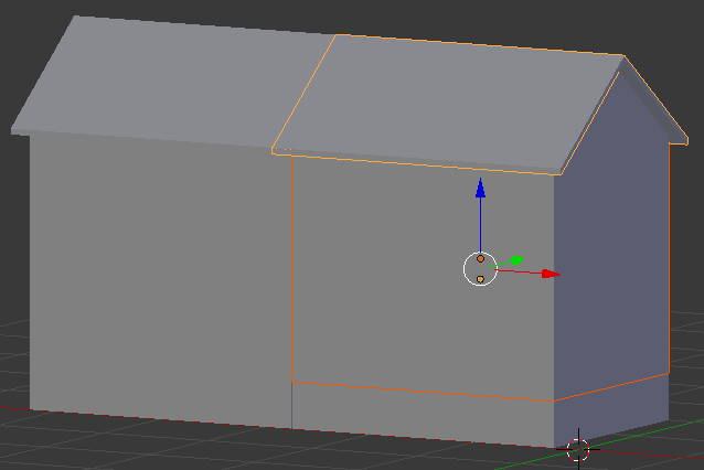
- In the Numeric Pad, press 3 to display the right view
- In the Numeric Pad, press 5 to work in orthogonal projection
- Move the roof down to the top of the house:

- In the Numeric Pad, press 1 to display the front view
- While the roof is selected, press and hold Shift
- Right-click the body of the mouse to add it the selection
- Right-click the bottom cube (the foundation) to add it the selection
- Release Shift:
Practical Learning: Starting Townhouses
- While the selection is still made, press Shift + D to copy
- Press X to move the duplicate horizontally
- Move the new house to the right of the other:
- Select the body of the new house and its roof:
- Press S to resize it
- Press Z to resize it only by its height
- Move the mouse slightly down to shrink it, and click:
- Move the mouse a little bit down to align its bottom border to the top border of the foundation. Here is an example:
- Move the view so you can see the house in perspective
- Add the second foundation to the selection and move the group a little behind the front line. Here is an example:

- Right-click the first foundation to select it
- Press and hold Shift
- Right-click the body of the first house
- Right-click the first roof
- Release Shift
- Press Shift + D to copy the selection
- Press X to move horizontally
- Move the new house to the right of the others and a position it so its front is aligned between the front of the first house and the front of the second house. Here is an example:


- Right-click the first foundation to select it
- Press and hold Shift
- Right-click the body of the first house
- Right-click the first roof
- Release Shift
- Press Shift + D to copy the selection
- Press X to move horizontally
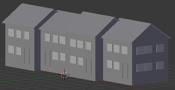
- Move the new house to the right of the others and a position it so its front is aligned behind the fronts of the other houses. Here is an example:
Practical Learning: Modeling a Window
- On the menu bar of the 3D View, in the Visible Layers section, click the second button
- Zoom in to have a large face facing you
- Right-click the box to select the cube:

- Press Tab to display in Edit Mode
- On the menu bar of the 3D-View, click the Face Select button if necessary
Right-click a large face to select it
- Press I to create an inset on the selected face
- Type .15 and press Enter:
- Press E to extrude
- Type -.095 and press Enter:
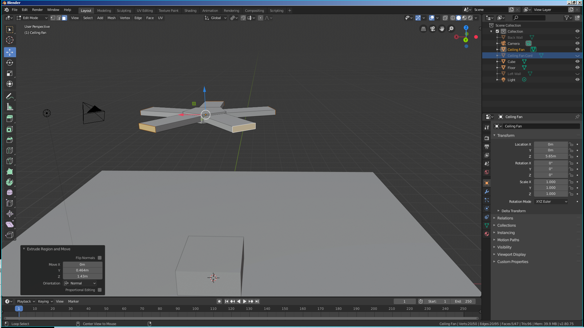
- While the face is still selected, press P to separate

- In the menu that appears, click Selection
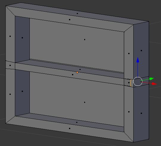
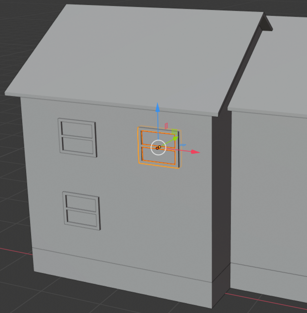
- Press Ctrl + R and make sure you get a horizontal cut on the window, then roll the middle mouse button to get two cuts:

- Click twice to confirm the cuts
- While the cuts are still selected, press S to move them
- Press Z to move vertically
- Type .2 and press Enter:

- On the menu bar of the 3D View, click the Face Select button
- Right-click one of the small interior faces:
 z
z
- Press E
- Using the red arrow, move the small face to the opposite border:
- On the menu bar of the 3D View, click Edit Mode and select Object Mode
- Right-click inside the window to select the face that was separated
- While the face is still selected, in the Properties window, click the Object button, click Small Window.001, type Window Glass and press Enter
- In the Numeric Pad, press 1 and press Z to display the wireframe
- Press S to resize it
- Type 1.1 and press Enter:

- Move the view to see the window in orthogonal view
- Press Z to exit the wireframe
- While the window glass is still selected, use the green arrow of the Y axis to move it close to the outiside face. Here is an example:

- While the window glass is still selected, press and hold Shift
- Right-click one of the borders of the window to select the whole window
- Release Shift
- Press Shift + D to copy them and press Enter
- Zoom out to see less of the windows
- Press M and, in the Move to Layers window, click the first button
- In the menu bar of the 3D View, click the first button of the Visible Layers section
Practical Learning: Creating Townhouses
- While the window and its inside are selected, move the window so you can see the plane inside it (the glass of the window). Here is an example:
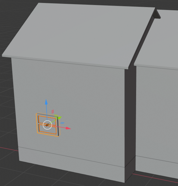
- While the window and its inside are selected, press Shift + D to copy them
- Press Z to move the copy vertically
- Move the window up (no need for precision, you will adjust everything later):
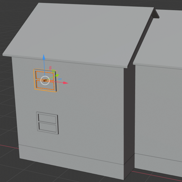
- While the window and its inside are selected, press Shift + D to copy them
- Press X to move the copy horizontally
- Move the window right (no need for precision, you will adjust everything later):
- On the menu bar of the 3D View, click Add -> Mesh -> Cube
- While the cube is selected, in the Properties window, click the Object button and change the following values:
Name:      Door Frame
Location - X: -3.25
           Y:  -5
           Z: .9
Scale    - X: .28
           Y: .05
           Z: .5
- Position the mouse in the work area and press Tab to enter into Edit Mode
- Press Ctrl + R and get a vertical cut
- Click once and move it to the left
- Click a second time to confirm
- In the same way, create another vertical cut on the right side
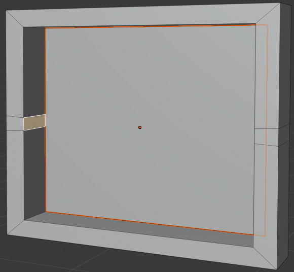
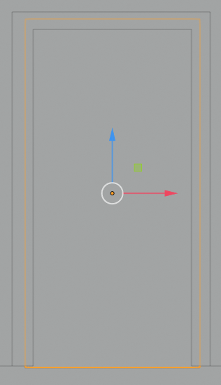
- In the same way, create a horizontal cut and move it to close to the top side:

- On the menu bar of the 3D View, click the Face Select button
- Right-click the inside face to select it
- Press E to extrude
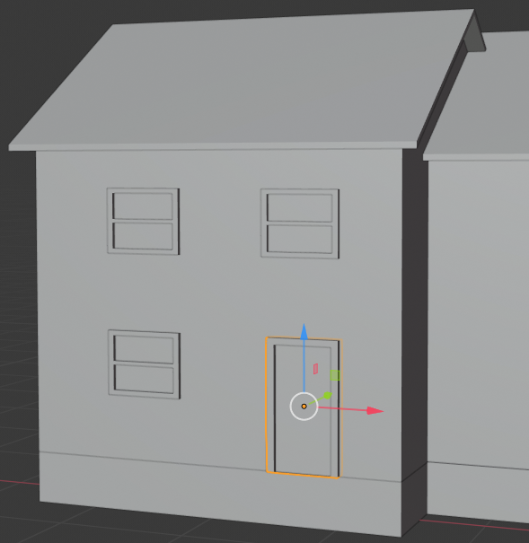
- Use the green arrow of the Y axis to move the face back. Here is an example:

- Press Tab to work in Object Mode
- Use the green arrow of the Y axis move the door to the front wall of the house:
- In the Create tab of the Tools window, click Plane
- In the Properties window, change the following values:
Name:      Door Face
Rotation - X: 90
- Move the plane to the door and resize it to fit inside the door. Here is an example:
- Select a window frame and the glass inside it
- Press Shift + D to copy the selection and press Enter
- Press R to rotate the selection
- Press Z to rotate horizontally
- Type -90 and press Enter
- Use the red arrow of the X axis to move the window to a side of an end house
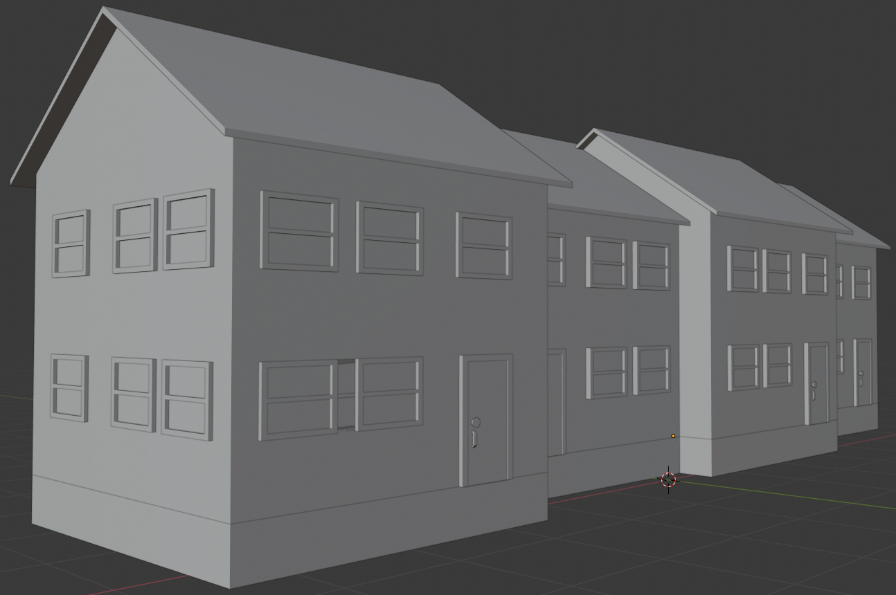
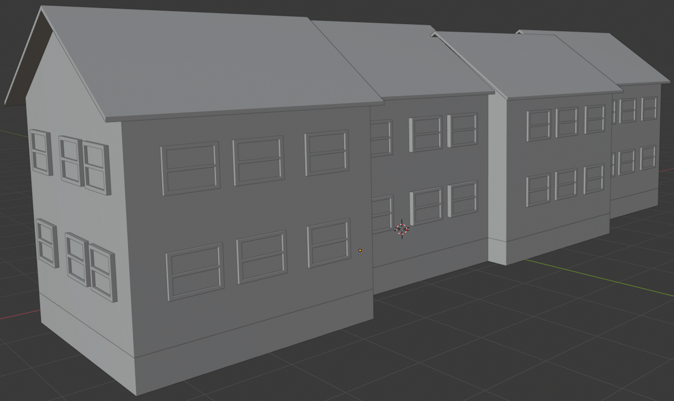
- By duplicating and moving windows and doors, complete the design to adding windows and a door to each townhouse. The placements of windows and doors don't have to follow the same pattern:

- Select a window frame and the glass inside it
- Press Shift + D to copy the selection and press Enter
- Press R to rotate the selection
- Press Z to rotate horizontally
- Type 180 and press Enter
- Use the green arrow of the Y axis to move the window to the other side of the house
- In the same way, add windows to the backs of the houses. Add windows to the side of an end house. Here are examples:
Practical Learning: Creating a Walkway
- In the Tools window, click the Create tab
- In the Create tab of the Tools window, click Cube
- In theObject tab of the Properties window, in the Transform section, change the following values:
Name:      Outside Stairs
Location - X: -3.25
           Y: -1
           Z: .2
Scale:     X: .35
           Y: .55
           Z: .2
- On the menu bar of the 3D View, click Object Mode and click Edit Mode
- Press Ctrl + R and get a vertical cut along the X axis
- Roll the mouse to get two cuts:

- Press Ctrl + R and get a horizontal cut along the Y axis
- Roll the mouse to get two cuts:
- Press Ctrl + Tab and click Face
- Right-click the top left face to select it
- Press X and click Faces
- In the same way, delete the faces that would not be used for stairs:

- Press Ctrl + Tab and click Edge
- Select two vertical opposing edges:

- Press F to join the edges into a face
- In the same way, select edges and create faces to complete the stairs:
- Press Tab to switch to Object Mode
- On the menu bar of the 3D View, click Add -> Mesh -> Cube
- In the Object section of the Properties window, in the Transform section, change the following values:
Name:	     Walkway
Location - X: -1.5
           Y: -2
           Z: .01
Scale:     X: 11
           Y: .5
			 Z: .02
- Right-click the stairs to select them
- Press Shift + D to copy
- Press X to move the selection
- Move the new stairs and position them in from of the door of the next house
- In the same way, add the stairs in front of the doors of the other houses:
- Position the mouse in the work area and press Shift + A -> Mesh -> Plane
- In the Object section of the Properties window, in the Transform section, change the following values:
Name:      Parking and Road
Location - X: 0
           Y: -5.5
           Z: .02
Scale:     X: 9.5
           Y: 3
- In the Create tab of the Tools window, click Plane
- In theObject tab of the Properties window, in the Transform section, change the following values:
Name:      Grass
Location - X: -5
           Y: 5.5
           Z: .01
Scale:     X: 15.5
           Y: 10
- In the Numeric Pad, press 0 to display the camera view
- Press N to display the Properties Region
- In the Properties Region, click Lock Camera to View
- Use the buttons on the mouse and the keyboard to get a better view. Here is an example:

- In the Properties region, click Lock Camera to View
- Press N to close the Properties region
Creating a World
The shader used to manage the world environment is named Background. This Background shader should not be used for other objects, only to create and manage the world environment.
Practical Learning: Introducing the World
- In the top menu bar, click Blender Render and select Cycles Render
- In the Properties window, click the Render button

- In the Resolution section, click 50% to select, type 100 and press Enter
- Click Sampling to expand it
- In the Samples section, set the Render value to 500
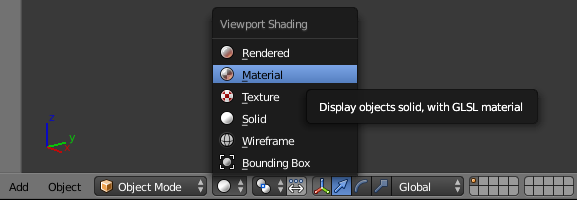
- On the menu bar of the 3D View, click the Viewport Shading button and select Material:
- In the Properties window, click the Material button

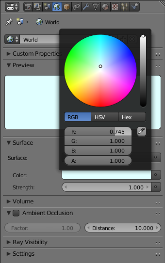
- In the Properties window, click the World button

- Below it, click Preview to expand it
- Click Use Nodes.
Notice that the shader in the Surface text box is set to Background
- Click the Color button and click RGB
- Set the color value as follows:
R: .745
G: 1
B: 1
- On the top menu, click Render -> Render Image to preview the result. Here is an example:

- After viewing the result, press Esc to close the render view
Practical Learning: Applying Primary Materials
- Right-click the roof of the left house
- In the Material section of the Properties window, click the New button
- Double-click Material.001 to edit it
- Type Gray Shingles and press Enter
- Click the Color button and set the color value as follows:
R: .303
G: .303
B: .293
- Right-click the roof of the second house to select it
- In the Material tab of the Properties window, click the button on the left side of New and select Gray Shingles
- Apply the same material to the roofs of the other two houses
- Right-click the body of the left house to select it
- In the Material section of the Properties window, click the New button
- Click Material.001 to select the name
- Type Red Hamilton and press Enter
- Click Color and set the color as follows:
R: .255
G: .065
B: .005
- Right-click the body of the second house to select it
- In the Material section of the Properties window, click the New button
- Click Color and set the color as follows:
R: .75
G: .45
B: .25
- Right-click the body of the third house to select it
- In the Material section of the Properties window, click the New button
- Click the Color button and set the color as follows:
R: .5
G: .15
B: .015
- Right-click the body of the fourth house to select it
- In the Material section of the Properties window, click the New button
- Click Material or Material.00X to select the name
- Type Dark Brown and press Enter
- Click the Color button and set the color as follows:
R: .285
G: .045
B: .015
- In the work area, right-click the border of one of the windows of the first house to select it
- In the Material section of the Properties window, click either New or Use Nodes
- Click the Color button and change the color as follows:
R: .105
G: .015
B: .005
- Right-click the inside of a window
- In the Material section of the Properties window, click the + button on the left side of Data
- In the Properties window, click Dark Brown.001 to select the name
- Type Glass and press Enter
- Click the Color button and set the color value as follows:
R: .675
G: .828
B: 1
- Apply that glass color to the inside of all windows of all the houses:

- In the work area, right-click the border of one of the windows of the second house
- In the Material section of the Properties window, click the + button on the left side of Data
- Click Material or Material.001 to select the name
- Type Orange and press Enter
- Click the Color button and change the color as follows:
R: 1
G: .25
B: .075
- Apply that color to the frames of all the windows of the second house
- In the work area, right-click the border of one of the windows of the fourth house
- In the Material section of the Properties window, click the button on the left of New and select Burly Wood
- Apply that Burly Wood color to the frames of all the windows of the fourth house:

- Right-click inside the door of the first house to select its face (you may have to right-click more than once until the inside face is selected). After selecting it, use the green arrow of the Y axis to move the face to the front so you can see it:

- In the Material section of the Properties window, click the New button
- Click the Color button and set the color as follows:
R: .296
G: 0
B: 0

- Right-click the door frame (the border) of the first house to select it
- In the Material section of the Properties window, click the New button
- Click the Color button and set the color as follows:
R: .8
G: .425
B: .05

- Right-click the door frame of the second house to select it
- In the Material section of the Properties window, click the New button
- Click the Color button and set the color as follows:
R: .015
G: .185
B: .8
- Right-click inside the door of the second house to select its face. Use the green arrow of the Y axis to bring it to the front
- In the Material section of the Properties window, click the New button
- Click the name of the material to select it
- Type Deep Yellow and press Enter
- Click the Color button and set the color as follows:
R: .525
G: .315
B: .085
- Right-click inside the door of the third house to select its face. Use the green arrow of the Y axis to bring it to the front
- In the Material section of the Properties window, click the button on the left side of New and select Dark Brown
- Right-click the door frame of the third house to select it
- In the Material section of the Properties window, click the New button
- Click the Color button and set the color as follows:
R: .7
G: .635
B: .6
- Right-click inside the door of the fourth house to select its face. Use the green arrow of the Y axis to bring it to the front
- In the Material section of the Properties window, click the New button
- Click the Color button and set the color as follows:
R: .8
G: .235
B: .125
- Right-click the door frame of the fourth house to select it
- In the Material section of the Properties window, click the New button
- Click the Color button and set the color as follows:
R: .8
G: .045
B: .045
- Right-click the foundation of any house (the cube below the body of any house) to select it
- In the Material section of the Properties window, click the New button
- Click Material.00X to select the name
- Type Cement and press Enter
- Click the Color button and set the color as follows:
R: .255
G: .255
B: .255
- Right-click the stairs in front of any house to select it
- In the Material section of the Properties window, click the button on the left side of New and select Cement
- Apply the Cement material to every foundation and all stairs of all the houses:

- In the Outliner, click Grass to select it
- In the Material section of the Properties window, click the New button
- In the Properties window, click Material.003 to select the name
- Type Regular Green and press Enter
- Click the Color button and set the color value as follows:
R: 0
G: .142
B: 0
- In the Outliner, click Walkway to select it
- In the Material section of the Properties window, click the button on the left side of New and select Cement
- In the Outliner, click Parking and Road
- In the Material section of the Properties window, click the New button
- Click the Color button and set the color value as follows:
R: .125
G: .125
B: .125
:
- In the Properties window, click the Render button
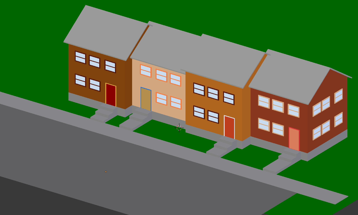
- In the Render section, click the Render button:

- After viewing the results, press Esc